The Paramco MIM Design Guide conveys in an easy-to-understand way the important information and support to the design engineers who work with MIM parts. Here you can find tips and assistance regarding parts design, processing tolerances, material specifications, and design suggestions.
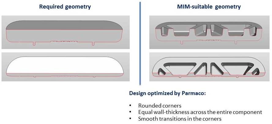
- Edges should be rounded if possible in order to improve flow behavior, reduce notch effects, stress peaks, and the risk of cracks formation.
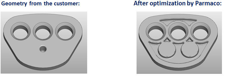
- For the same reasons, corners should be rounded if possible, too.
- Material accumulation should be avoided if possible. This does not only lower costs and weight, but also reduces the risk of shrinkholes, sink marks and internal tension. It also reduces the time needed for the molding process.
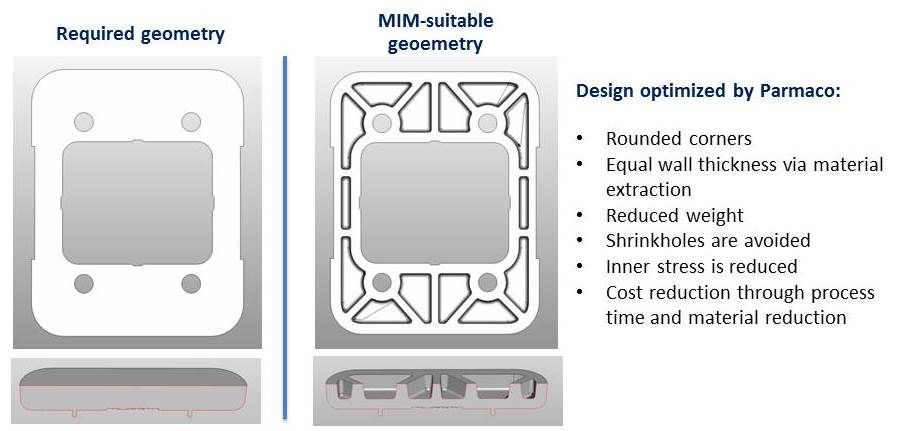
- The whole component should have a constant wall thickness.
- Material accumulations lead to shrinkholes, sink marks and distortion. They also worsen the tolerances, causing more expenditure in calibration and coining.
- Transitions should be smoothly shaped if possible.
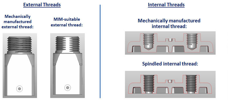
- External threads are relatively easy to produce by the injection molding process. A flattening should be provided in the parting plane to avoid the negativ effect on the clearance of the thread.
- Internal threads are created using a movable core, which is not just pulled out, but “unscrewed” using an unscrewing device.
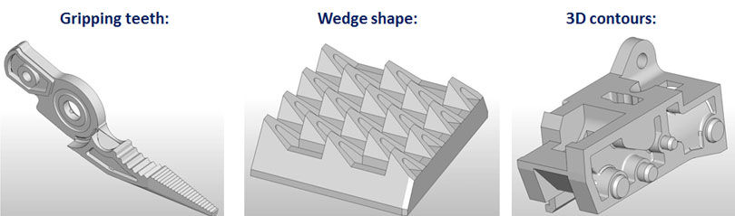
- Using the core with the right shape, one can create nearly any contour in holes and gaps such as round perforations, square bores, hexagon sockets, torx, etc. In doing so, very complex profiles are possible as well. Both clearance holes and blind holes are possible.
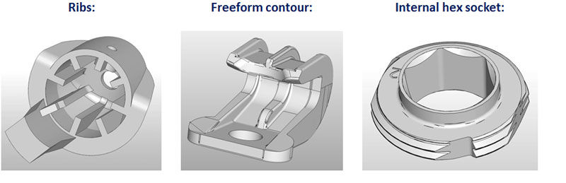
- The MIM process enables the burr-free production of complex surface profiles. The only prerequisite is that the corresponding geometry must be demoldable.
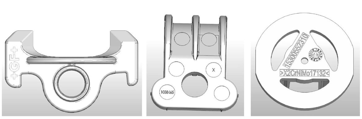
There are multiple possibilities regarding labelings and engravings:
- Labeling protruding or recessed
- Company logos
- Symbols
- Article numbers
- Text fields & warnings
- Production date (month, year)
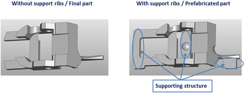
- Avoided distortion by self-contained geometry of the parts
- Avoided distortion by applying a support structure to part
The extra freedom of the design engineer is one of the special advantages of the MIM process. It often happen that parts, which are requested as MIM parts are originally designed as turned/milled parts. This means that certain restrictions, given the fact that the possibilities and restrictions of this machining process are obejed, are designed into the part. Thus, for example, the contours which are set in the direction of the longitudinal axis are usually designed in cylindrical shape, because that shape is the easiest to process with the turning machines. With the MIM process, however, one can benefit from the advantages of geometrical freedom which is only governed by the function of the component, nearly free of cost. Facets, material gaps, non-round holes, adjusting patterns, etc. can be generated simultaneously in the process without additional costs. By a general adjustment of the wall thickness to 2mm, one creates ideal conditions for filling the part with injection molding. At the same time the costs are lowered considerably.